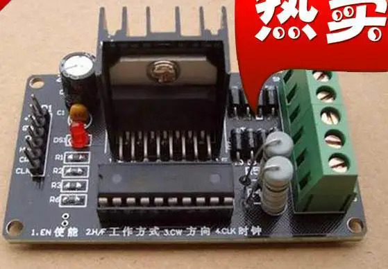
Stepper Motor Driver Ic L297 Stepper

The L297 integrates all the control circuitry required to control bipolar and unipolar stepper motors. Used with a dual bridge driver such as the L298N forms a complete microprocessor-to-bipolar stepper motor interface. For example The L297, takes the signals from your microprocessor and translates them into stepping signals to send to the L298 which actually drives your stepper motor. The L298 is capable of driving up to 2A per coil. One interesting feature of the L297 is its current sensing and 'chopping' abilities. The L297 will sense the amount of current flowing through the coils, and will 'chop' the signal to the L298 so that the average current flowing is the desired amount. You can configure this current by setting the trimpot on the board and measuring the voltage on the test point.
For L297 Datasheet, For L297 Application notes.
Technically stepper motor driver circuit is a Decade Binary Counter circuit. Basics Of Web Design Html5 & Css3 2nd Edition Pdf. The advantage of this circuit is, it can be used to drive stepper motors having 2-10 steps. Before going any further let’s discuss more about the basics of stepper motor. The name of this motor is given so because the rotation of shaft is in step form which is different from DC or any other motor. In other motors the speed of rotation, the stop angle are not in complete control unless necessary circuit is inserted. This non-control is present because moment of inertia, which is simply a character to start and stop on command without delay. Consider a DC motor, once its powered the speed of motor increases slowly until it catches the rated speed.
® L297 STEPPER MOTOR CONTROLLERS. The L297 Stepper Motor Controller IC generates. 5 INH1 Active low inhibit control for driver stage of A and B phases. All About Stepper Motors. And off in sequence to energize the phases and step the motor. Change Setup Icon Advanced Installer Project there. Unipolar drivers are relatively inexpensive to build.
Now if a load is put on the motor, the speed decreases over the rated and if load is further increased the speed further decreases. Now if the power is turned off the motor does not come to halt immediately as it will have moment of inertia, it stops slowly. Now consider this is a case in a printer the paper outflow does not stop in time, we lose paper every time we start and stop. We need to wait for the motor to pick the speed and due time the paper is lost. This is unacceptable for most of the control systems, so to solve this kind of problems we use stepper motors. The stepper motor does not work on constant supply. It can only be worked on controlled and ordered power pulses. Before going any further we need to talk about UNIPOLAR and BIPOLAR stepper motorS.
As shown in figure in a UNIPOLAR stepper motor we can take the center tapping of both the phase windings for a common ground or for a common power. In first case we can take black and white for a common ground or power. In case 2 black is take for a common. In case3 orange black red yellow all come together for a common ground or power.
In BIPOLAR stepper motor we have phase ends and no center taps and so we will have only four terminals. The driving of this type of stepper motor is different and complex and also the driving circuit cannot be easily designed without a microcontroller.
The circuit which we designed here can only be used for stepper motors of UNIPOLAR type. The power pulsing of UNIPOLAR stepper motor will be discussed in circuit explanation. Circuit Components • +9 to +12 supply voltage • 555 IC • 1KΩ, 2K2Ω resistors • 220KΩ pot or variable resistor • 1µF capacitor, 100µF capacitor (not a compulsory, connected in parallel to power) • 2N3904 or 2N2222 (no. Of pieces depend on type of stepper if it’s a 2 stage we need 2 if it’s a four stage we need four) • 1N4007 (no.
Of diodes is equal to no. Of transistors) • CD4017 IC,. Stepper Motor Driver Circuit Diagram and Explanation The figure shows the circuit diagram of two stage stepper motor driver. Now as shown in the circuit diagram the 555 circuit here is to generate clock or the square wave. The frequency of clock generation in this case cannot be kept constant so we need to get variable speed for the stepper motor. To get this variable speed a pot or a preset is paced in series with 1K resistor in branch between 6 th and 7 th pin. As the pot is varied the resistance in the branch changes and so the frequency of clock generated by 555. In the figure the important thing is only the third formula.
You can see that the frequency is inversely related to R2 (which is 1K+220k POT in the circuit). Just Dance Videos Download Mp4. So if R2 increases the frequency decreases.
And so if the pot is adjusted to increase the resistance in the branch the frequency of clock decreases. The clock generated by is fed to DECADE BINARY counter. Now the decade binary counter counts the number of pulses fed at the clock and lets the corresponding pin output go high.
Posts
- Musik Download German Top 100 Single Charts 2014 Cannapower Search
- Download Free Software Autek Research Va1 Manual Meat
- Net Collection Tw
- Tomtom Maps Central And Eastern Europe Download Skype
- Download Game Pokemon Emerald Version 2
- Contoh Program Inventory Berbasis Webassign
- Vw Touareg Navigation Rns2 Cd Download
- Download Sach Barron Essential Words For The Toefl Itp
- Download Mame Rom Pack Zip
- Synergy Keygen Music
- Drivers License Jacksonville Fl Kernan
- Me Without You 2001 Download Chrome